
Lead-Acid Batteries are one of the oldest and most widely used energy storage technologies, yet they remain critically important in modern society. Invented in 1859, they are still the dominant battery type for automotive starting, lighting, and ignition (SLI) systems. Virtually every internal combustion vehicle relies on a lead-acid battery to deliver the high surge current needed to start engines reliably.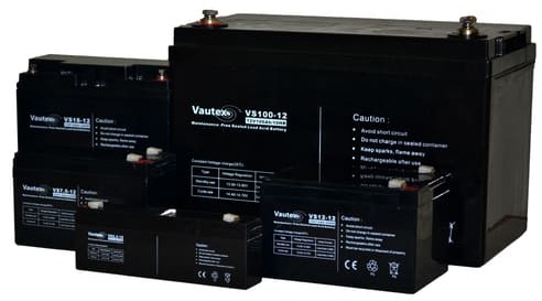
Beyond vehicles, lead-acid batteries are extensively used in backup power systems. They provide uninterruptible power supply (UPS) support for hospitals, data centers, telecommunications infrastructure, and emergency lighting systems. Their ability to deliver stable, dependable power during outages makes them essential for safety and continuity in critical operations.
A major benefit of lead-acid batteries is their robustness and cost-effectiveness. They are relatively inexpensive to manufacture compared to newer chemistries like lithium-ion, and they perform well across a wide range of temperatures. Additionally, they are highly recyclable—over 95% of a lead-acid battery can be recovered and reused—making them one of the most successfully recycled products globally.
Their simplicity, reliability, and established recycling infrastructure make lead-acid batteries especially valuable in developing regions, where they support off-grid energy storage and renewable systems such as solar installations, contributing to global energy access.
Electrochemical Architecture
These batteries are based on lead alloy grid technology, which replaces traditional antimony alloys. The content significantly reduces water loss via electrolysis, enabling a low-maintenance or semi-sealed configuration.
The fundamental electrochemical reactions remain: 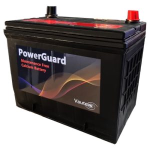
Discharge: PbO₂ + Pb + 2H₂SO₄ → 2PbSO₄ + 2H₂O
Charge: (Reverse reaction) restores active materials.
The alloy reduces self-discharge rates and improves corrosion resistance, particularly at the positive grid.
Grid & Plate Manufacturing
From a production standpoint:
Grids: Typically cast using continuous casting or expanded metal processes, with tight control of content (~0.06–0.1%) to balance mechanical strength, corrosion resistance, and conductivity.
Positive Plates: Use high-density lead dioxide paste optimized for high surface area (improved reaction kinetics) and mechanical adhesion (reduced shedding under vibration).
Negative Plates: Incorporate carbon additives in some designs to improve charge acceptance and reduce sulfation under partial state-of-charge (PSOC) conditions.
Electrolyte & Separator Design
Semi-sealed units still contain liquid electrolyte, but with:
Reduced free electrolyte volume (compared to flooded batteries).
Use of microporous polyethylene separators featuring high puncture resistance and controlled ionic permeability.
This configuration allows limited recombination while maintaining high current output.
Technology (CCA Optimization)
From a design perspective, high cold cranking performance (CCA) is achieved through:
Low Internal Resistance (Ri): Achieved via shorter current paths and optimized grid geometry.
Increased Surface Area: Higher plate count per cell increases the reactive surface area.
Conductivity Tuning: Electrolyte tuning for low-temperature operation.
CCA performance is directly tied to the ability to deliver high current under:
Low temperature (reduced electrolyte mobility).
High load (voltage drop constraints).
Mechanical & Structural Engineering
Polypropylene (PP) Casing: Injection-molded for chemical resistance to sulfuric acid and thermal stability.
Internal Ribbing: Reinforced ribbing improves vibration resistance (critical for automotive/industrial use).
Integrated Handles: Structurally reinforced to withstand full battery weight under dynamic loading.
Venting & Safety
Semi-sealed systems include pressure-relief vents calibrated to:
Release excess hydrogen/oxygen gases.
Prevent casing rupture.
Note: Unlike fully sealed VRLA systems, recombination efficiency is lower.
Performance Profile
High cranking current capability.
Moderate cycle life (~300–500 cycles depending on DoD).
Good tolerance to high current discharge and engine-starting applications.
Manufacturing Trade-offs
- Advantages: Lower production cost than AGM/Gel; simpler electrolyte filling process.
- Limitations: Not fully spill-proof; limited deep-cycle durability compared to VRLA advanced designs.
Electrochemical System
These batteries utilize Valve-Regulated Lead-Acid (VRLA) technology, typically with AGM (Absorbent Glass Mat) separators.
Key Difference: Electrolyte is immobilized in glass fiber mats, eliminating free liquid.
Oxygen Recombination Cycle 
A defining feature of this system:
During charging, oxygen evolves at the positive plate.
It migrates through the AGM separator to the negative plate.
Recombines to form water.
This mechanism achieves:
- 95% gas recombination efficiency.
Minimal water loss (maintenance-free design).
Separator Engineering (AGM)
AGM is a critical component made from boron-silicate glass fibers designed for:
High porosity (~90%).
Uniform electrolyte distribution.
Capillary action to retain electrolyte.
Manufacturing Challenge: Precise compression ratio must be controlled to ensure good plate contact and optimal ionic conductivity.
Plate Design Optimization
Thin Plate Construction: Allows for high energy density and a compact form factor.
Lead-Tin Alloys: Improve grid corrosion resistance and float life stability.
Sealing & Valve System
One-Way Pressure Valves: Typically 2–5 psi threshold to prevent air ingress (dry-out) and electrolyte loss.
Sealing Process: Involves ultrasonic welding of the case and lid, followed by leak testing under pressure differentials.
Thermal & Environmental Performance
Operating/Storage Range: -20°C to 50°C.
Low Temperatures: Considerations for reduced electrolyte mobility and increased internal resistance.
High Temperatures: Considerations for accelerated grid corrosion and increased recombination load.
Balance: Materials are selected to balance thermal expansion and electrochemical stability.
Electrical Characteristics
Nominal voltage: 12V (6 cells × 2V each).
Lower internal resistance than flooded equivalents.
Better charge acceptance.
Note: Limited peak discharge vs automotive batteries; designed for standby power and light cyclic use.
Applications & Engineering Fit
Optimized for UPS systems, alarm systems, telecom backup, and portable electronics.
Manufacturing Considerations
Requires clean-room-like conditions for AGM handling and tight control of electrolyte saturation levels and plate alignment.
Failure Modes (if poorly manufactured): Dry-out, stratification (less common), and early capacity loss.
Electrochemical System
These batteries are a subtype of Valve-Regulated Lead-Acid (VRLA) technology using a silica-gelled electrolyte.
Key Difference:
Electrolyte is immobilized by adding fumed silica (SiO₂), forming a semi-solid gel.
Oxygen Recombination Cycle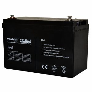
Similar to AGM but less efficient due to gel structure:
- Oxygen evolves at the positive plate during charging.
- Diffuses through micro-cracks in the gel.
- Recombines at the negative plate to form water.
Performance Characteristics:
- ~90–95% recombination efficiency (slightly lower than AGM)
- Minimal water loss → maintenance-free
- Slower gas diffusion → limits high charge rates
Electrolyte Engineering (Gel Structure)
The electrolyte is transformed via thixotropic gel formation:
- Silica creates a 3D matrix trapping sulfuric acid.
- Prevents electrolyte movement and stratification.
- Micro-cracking occurs during initial cycles, enabling ion transport.
Key Properties:
- High resistance to acid stratification
- Improved deep-cycle durability
- Lower ionic mobility vs AGM
Manufacturing Challenge:
- Precise control of silica concentration and mixing
- Avoiding voids and ensuring uniform gel distribution
Plate Design Optimization
Designed for deep-cycle performance:
- Thicker plates than AGM → improved cycle life
- Lead-calcium or lead-selenium alloys for corrosion resistance
- Lower surface area → reduced high-rate discharge capability
Sealing & Valve System
- Pressure relief valves: Typically 2–5 psi
- Prevents:
- Excess gas buildup
- Air ingress (which would oxidize plates)
Critical Constraint:
- Overcharging can cause irreversible gas pockets in gel → permanent capacity loss
Thermal & Environmental Performance
- Operating range: -15°C to 50°C
Low Temperatures:
- Gel stiffens → reduced ion mobility
- Increased internal resistance
High Temperatures:
- Risk of gel drying and structural breakdown
- Accelerated grid corrosion
Advantage:
- More stable under deep discharge thermal stress than AGM
Electrical Characteristics
- Nominal voltage: 12V (6 × 2V cells)
- Higher internal resistance than AGM
- Lower peak discharge capability
- Excellent deep discharge recovery
Charging Sensitivity:
- Requires lower charge voltages (typically ~14.1–14.4V)
- Sensitive to overvoltage → void formation
Applications & Engineering Fit
Optimized for:
- Solar energy storage
- Mobility (wheelchairs, golf carts)
- Marine deep-cycle use
Strength: Deep-cycle durability and resistance to stratification
Limitation: Not suited for high current or fast charging
Manufacturing Considerations
- Controlled gel mixing and filling process
- Degassing required before sealing
- Tight control of curing time for gel stabilization
Failure Modes
- Gel void formation (from overcharging)
- Dry-out (less common than AGM)
- Reduced capacity due to poor ion pathways
- Thermal cracking of gel structure
Electrochemical System
Traditional lead-acid system with free liquid electrolyte.
Key Difference:
Electrolyte (sulfuric acid solution) is fully liquid and freely movable within the cell.
Gas Evolution & Venting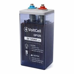
No recombination system:
- Charging produces:
- Hydrogen at the negative plate
- Oxygen at the positive plate
- Gases are vented to atmosphere
Implications:
- Water loss is continuous → requires maintenance
- Ventilation is critical (explosion risk)
Electrolyte Dynamics
Free-flowing liquid allows:
- High ionic mobility
- Efficient heat dissipation
Key Challenge: Acid Stratification
- Heavier acid settles at the bottom
- Leads to uneven plate utilization and sulfation
Mitigation:
- Periodic equalization charging
- Mechanical agitation (in some applications)
Plate Design Optimization
Designed depending on use case:
Starting Batteries (SLI):
- Thin plates → high surface area
- High cranking current
Deep Cycle Variants:
- Thicker plates → longer cycle life
Alloy Types:
- Lead-antimony (better cycling, higher water loss)
- Lead-calcium (lower maintenance, longer float life)
Container & Venting System
- Open or semi-sealed casing with vent caps
- Allows:
- Gas escape
- Water refilling
Engineering Trade-off:
- Simplicity vs environmental exposure and maintenance
Thermal & Environmental Performance
- Operating range: -20°C to 50°C
Low Temperatures:
- Electrolyte can freeze if discharged
- Reduced capacity
High Temperatures:
- Increased evaporation
- Accelerated corrosion
Advantage:
- Better heat dissipation than VRLA types
Electrical Characteristics
- Nominal voltage: 12V
- Lowest internal resistance among lead-acid types
- High surge current capability
Charge Acceptance:
- Tolerant of overcharging (with water replenishment)
- Can handle higher charge currents than Gel/AGM
Applications & Engineering Fit
Optimized for:
- Automotive starting (SLI)
- Industrial systems (forklifts)
- Large backup systems
Strengths:
- High current output
- Cost-effective
- Robust to charging abuse
Manufacturing Considerations
- Simpler production vs VRLA:
- Plate casting
- Electrolyte filling
- Formation cycling
- Less stringent sealing requirements
Failure Modes
- Sulfation (due to undercharging)
- Acid stratification
- Water loss → plate exposure
- Grid corrosion
- Shedding of active material